
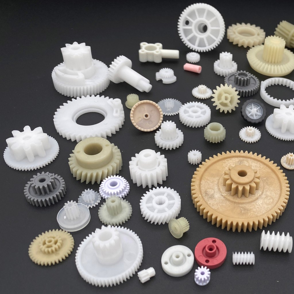
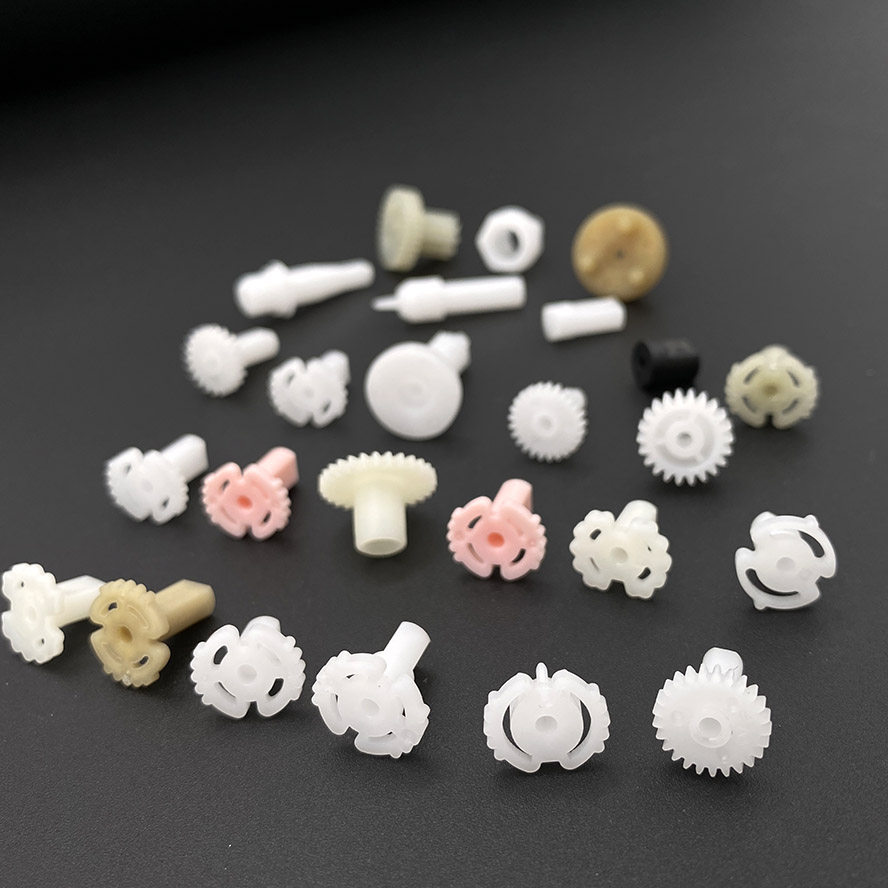
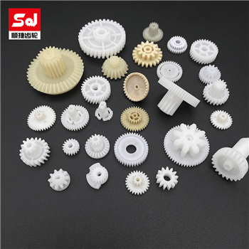
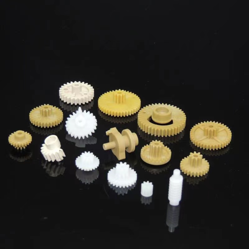
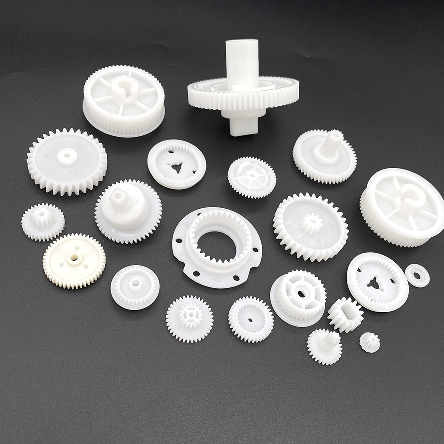
Plastic Gears
ISO 9001 Certified | OEM & Custom Manufacturing | 24-Hour Quotation
High Precision Plastic Gear Manufacturing
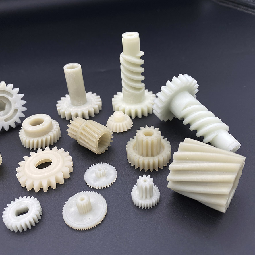
We manufacture high precision plastic gears using advanced injection molding and CNC machining technologies. Our plastic gears are widely used in automotive, robotics, medical devices and industrial systems, providing low noise, lightweight performance and excellent wear resistance. With strict tolerance control (±0.01mm) and stable mass production capability, our plastic gears are widely used in automotive, robotics, medical devices and industrial systems.
Key Specifications
Materials
Module
Tolerance
Process
Lead time
POM / Nylon / PPS / ABS
0.3 – 3
±0.01mm
Injection molding / CNC machining
15–30 days
Why Choose Our Plastic Gears
- ISO 9001 certified manufacturing
- Precision tolerance up to ±0.01mm
- Advanced injection molding equipment
- Engineering support for custom designs
- Stable quality for long-term mass production
- Fast quotation within 24 hours
Applications Industries We Serve
- Electric motors
- Robotics systems
- Medical devices
- Automotive components
- Consumer electronics
- Industrial gearboxes
Need Custom Plastic Gears?
Send us your drawings and specifications for a fast quotation within 24 hours.
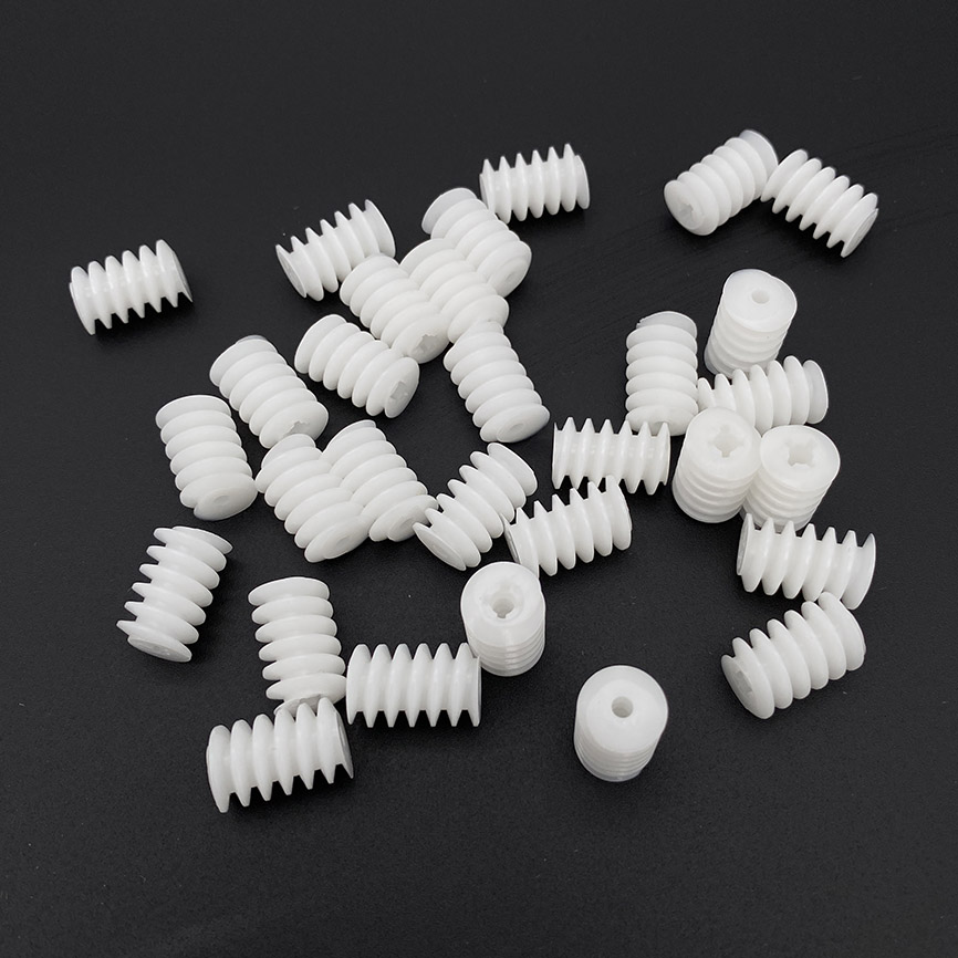
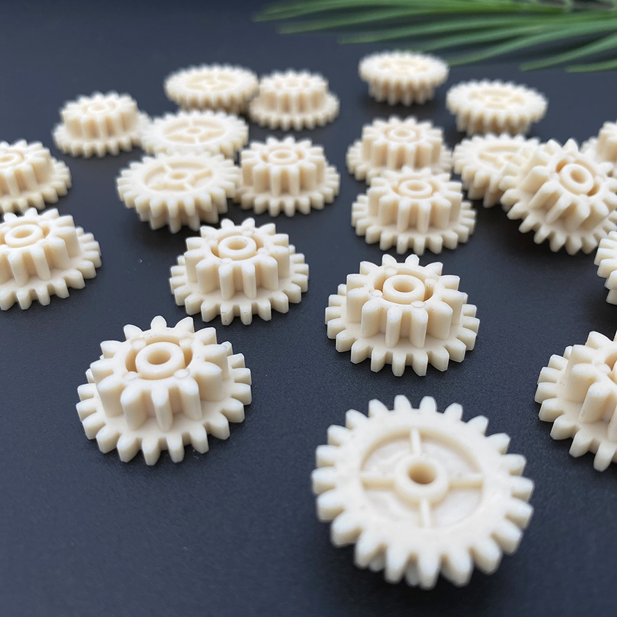
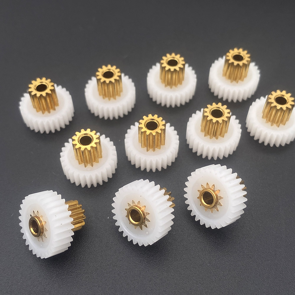
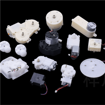
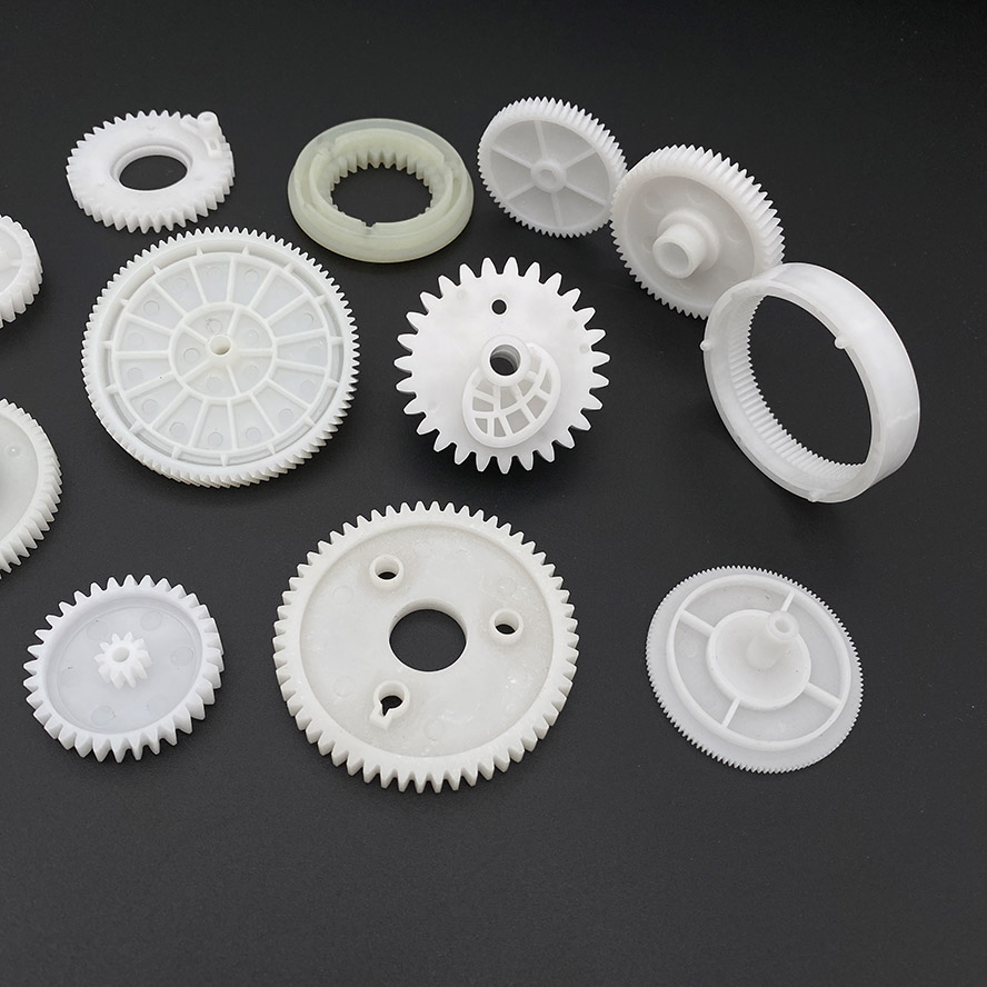
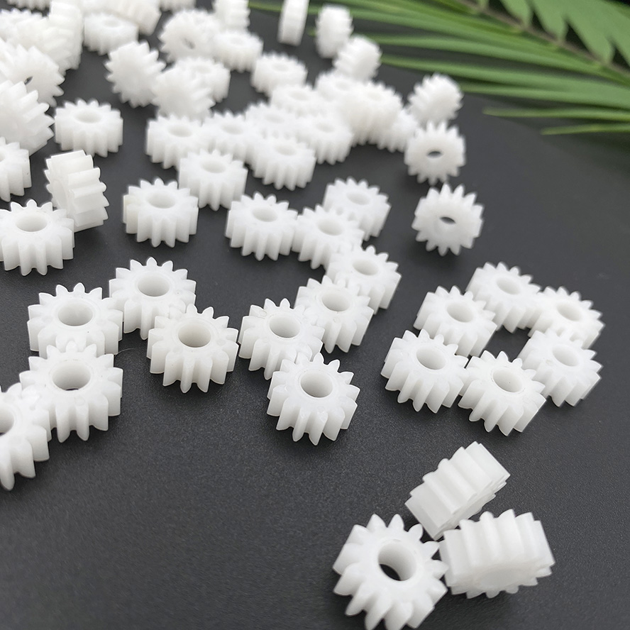
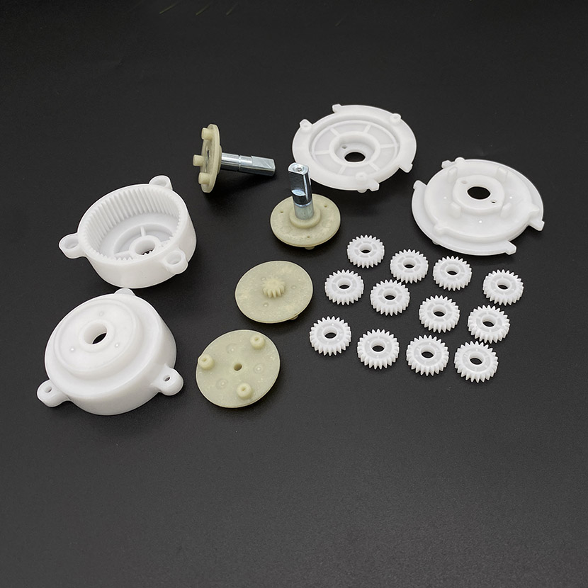
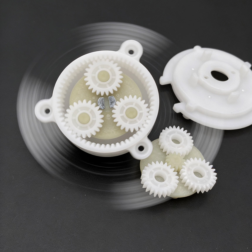
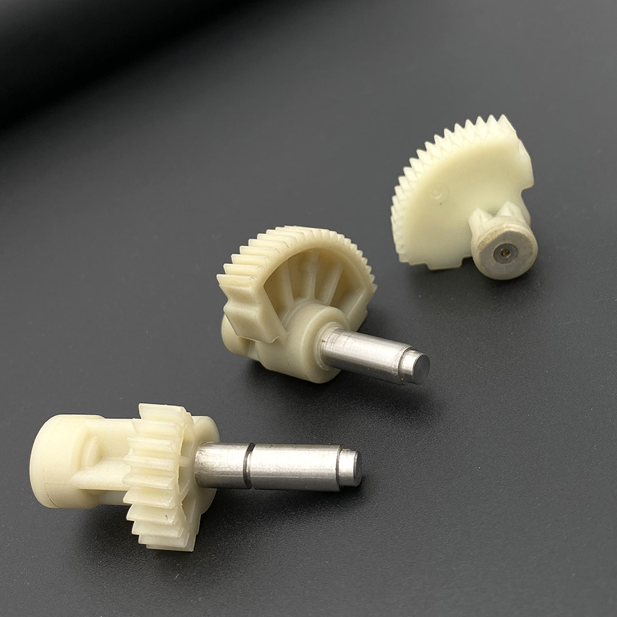
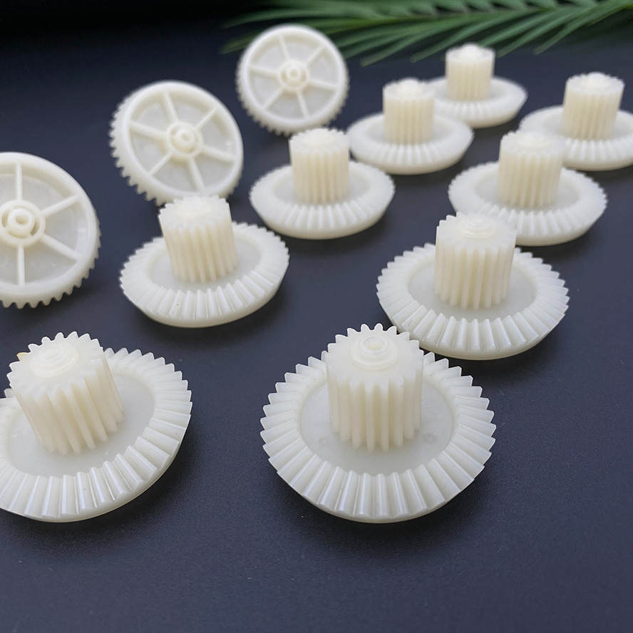
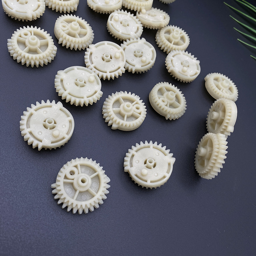
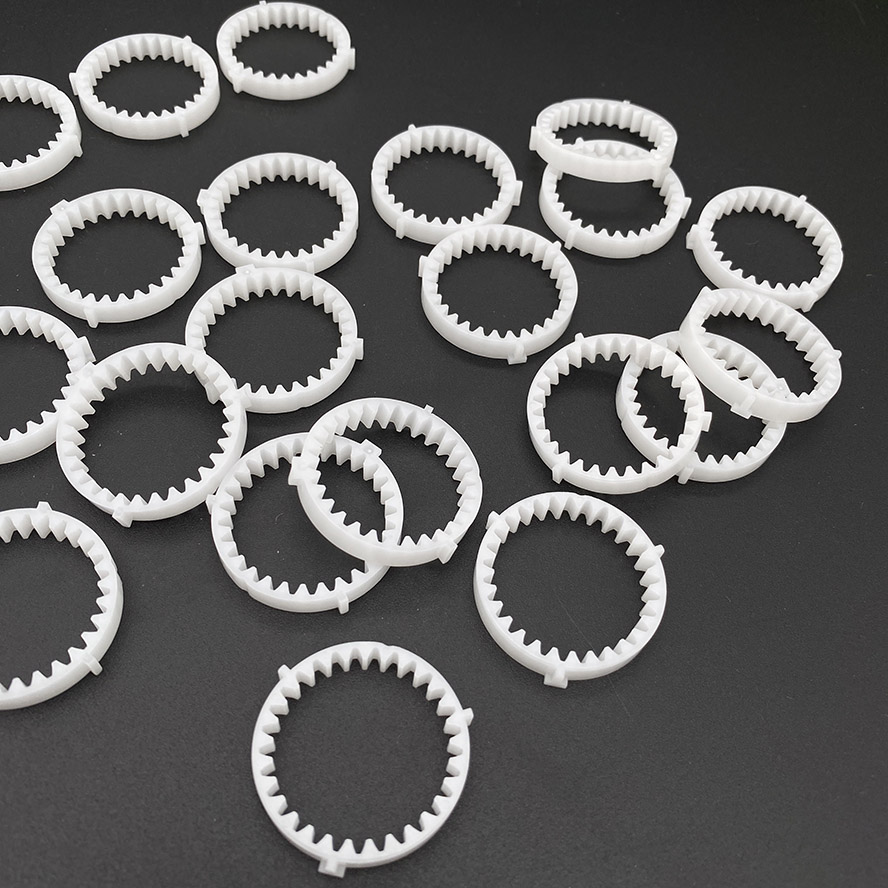
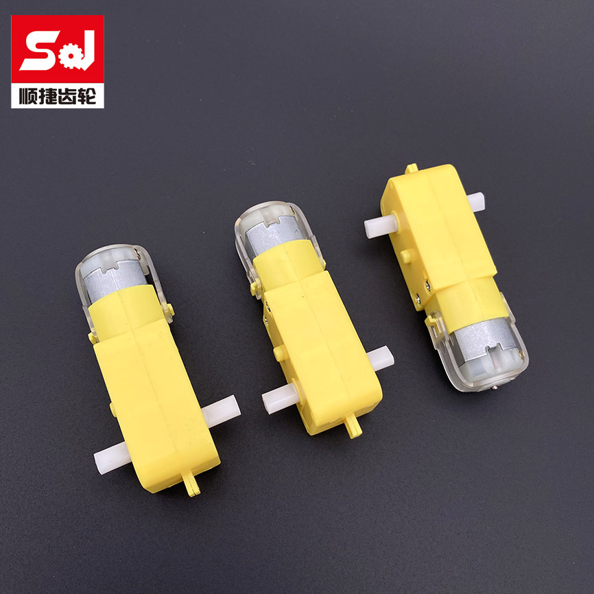
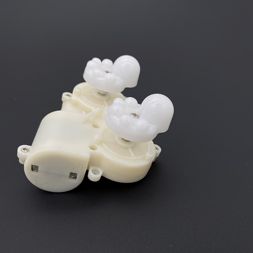
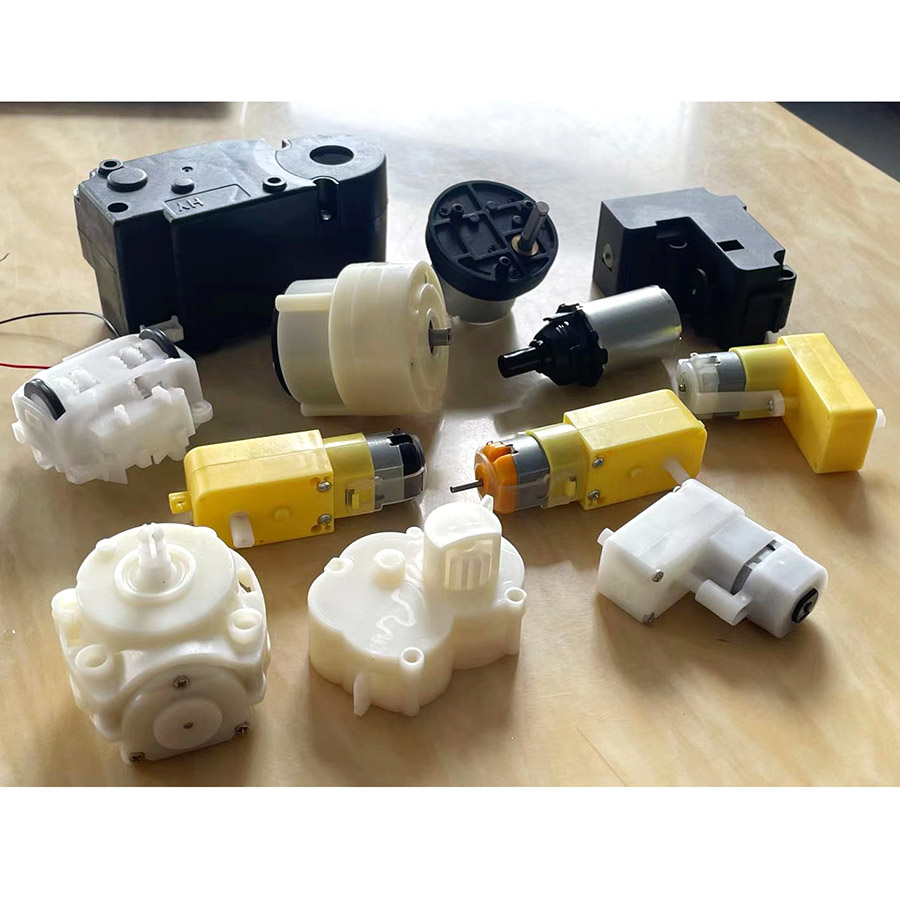
Productions

Engineering Insights
Dimensional Accuracy and Shrinkage Control Issues
Core Challenge
Fluctuations in the shrinkage rate of plastic materials (e.g., approximately 1.5%-2.5% for nylon, approximately 2.0%-2.5% for POM) can lead to gear dimensional deviations, making it difficult to meet the accuracy requirements for tooth profile and pitch, thus affecting meshing performance.
Solution
Accurate Calculation of Shrinkage Rate Based on material properties (e.g., melt flow rate, glass fiber filler ratio) and mold temperature, the shrinkage trend is simulated using mold flow analysis software (e.g., Moldflow), allowing for compensation dimensions.
Mold Temperature Balance Control
Utilizing conformal cooling channels (such as in 3D printed molds) ensures a temperature difference of ≤5℃ across the mold cavity, reducing localized shrinkage differences caused by uneven cooling.
Deformation and Warpage Issues
Core Challenges
Thin-walled gear structures (e.g., tooth tip thickness <0.5mm) are prone to warpage after injection molding due to stress concentration, leading to excessive tooth deviation (e.g., ISO precision requirement ≤0.01mm).
Solutions
Optimizing Gate and Runner Design
Using multi-point submarine gates (e.g., symmetrically distributed 2-4 points) reduces melt flow imbalance; trapezoidal runner cross-sections (wider at the top, narrower at the bottom) reduce pressure loss.
Process Parameter Control
Reduce injection speed (e.g., from 100mm/s to 50mm/s) to reduce shear stress; use stepped pressure during the holding pressure stage (e.g., hold at 90% for 10s, then at 60% for 5s) to alleviate residual stress.
Reduce injection speed (e.g., from 100mm/s to 50mm/s) to reduce shear stress; use stepped pressure during the holding pressure stage (e.g., hold at 90% for 10s, then at 60% for 5s) to alleviate residual stress.
Tooth Profile Accuracy and Mold Wear Issues
Core Challenges
Mold tooth profile machining errors (e.g., EDM roughness Ra > 0.8μm) are directly transmitted to the gear surface, and glass fiber filler materials (e.g., PA6 + 30% GF) are prone to mold wear during long-term injection molding, leading to a decrease in tooth profile accuracy.
Solutions
High-Precision 16Mold Machining Process
Use slow wire EDM (accuracy ±0.005mm) or five-axis CNC milling to machine the tooth profile, combined with optical projection detection (e.g., a 2D imaging system) to calibrate tooth profile deviations.
The mold surface is plated with hard chrome (5-10μm thickness) or18 coated with PVD (such as TiCN), increasing the hardness to HV1500+ and extending the wear life from 50,000 injection cycles to 200,000 cycles.
Material and Mold Matching Optimization
For high wear-resistance applications (such as copier gears), PEEK or PPS materials are selected, while the mold uses S136H pre-hardened steel (hardness HRC48-52) to reduce abrasive wear.
Venting and Material Shortage Issues
Core Challenges
The gear tooth grooves are narrow (e.g., approximately 0.75mm when the module m=0.5), making them prone to air trapping during melt filling, leading to material shortages at the tooth tips or surface bubbles, affecting strength and accuracy.
Solutions
Mold Venting System Design
Create venting grooves 0.02-0.03mm deep on the parting surface of the gear teeth, extending 0.5mm wide outside the mold; for complex tooth shapes, use permeable steel (such as PM-35) inserts with a permeability of 0.2μm.
Auxiliary Venting Process
Utilize vacuum injection molding technology (mold cavity vacuum ≤ -90kPa) to remove residual air; or install a gas-assisted device at the front end of the barrel to reduce melt filling resistance.
Demolding and Tooth Surface Damage Issues
Core Challenges
Precision gears typically have a draft angle ≤ 1° (to avoid affecting tooth profile accuracy), making them prone to tooth surface scratches or deformation due to friction during ejection.
Solutions
Molding Mechanism Optimization
Use a push plate ejection (instead of ejector pins) to ensure even force distribution on the gears; control the ejection speed at 5-10 mm/s to avoid impact deformation.
Mirror polish the mold surface (Ra≤0.2μm) and apply a fluorosilane release agent, reducing the coefficient of friction from 0.3 to below 0.1.
Tooth-Shape
d MoldinFor helical gears (helix angle >15°), use a rotary molding mechanism (such as a rack and pinion drive) to rotate along the tooth direction to avoid scratching. For example, this improves the molding efficiency of power tool gears by 30%.g Design
Molding Cycle and Production Efficiency Issues
Core Challenges
High-precision gears require long cooling times (e.g., ≥30s), resulting in low production efficiency (single mold cycle >60s).
Solutions
Rapid Cooling Technology
Use a temperature differential circulation system (e.g., 80℃ for the front mold and 40℃ for the rear mold) to shorten cooling time to 15-20 seconds; or use a hot runner mold (temperature control ±1℃) to reduce melt heat loss.
Multi-Cavity Mold Design
For small gears (diameter <10mm), use 16-32 cavity molds, combined with a servo injection molding machine (positioning accuracy ±0.01mm), increasing single-mold output by 4-8 times and reducing costs by more than 50%.
